<?xml version="1.0" encoding="utf-8"?><feed xmlns="http://www.w3.org/2005/Atom" ><generator uri="https://jekyllrb.com/" version="3.10.0">Jekyll</generator><link href="https://lucasbucht.github.io/feed.xml" rel="self" type="application/atom+xml" /><link href="https://lucasbucht.github.io/" rel="alternate" type="text/html" /><updated>2026-09-08T12:34:10+00:00</updated><id>https://lucasbucht.github.io/feed.xml</id><title type="html">Lucas Bucht</title><subtitle>Personal portfolio and blog, built with Jekyll, hosted on GitHub Pages.</subtitle><author><name>Lucas Bucht</name><email>buchtlu@gmail.com</email></author><entry><title type="html">How I Made: Guitar Fuzz Pedal</title><link href="https://lucasbucht.github.io/blog/2026/07/12/fuzz-pedal/" rel="alternate" type="text/html" title="How I Made: Guitar Fuzz Pedal" /><published>2026-07-12T00:00:00+00:00</published><updated>2026-07-12T00:00:00+00:00</updated><id>https://lucasbucht.github.io/blog/2026/07/12/fuzz-pedal</id><content type="html" xml:base="https://lucasbucht.github.io/blog/2026/07/12/fuzz-pedal/"><![CDATA[<hr />

<h3 id="backstory">Backstory</h3>
<p>I started playing guitar 3 years ago, and one of the things that fascinated me the most when I 
started was testing out different pedals. I was blown away by the different sounds you could 
achieve using discrete components and an analog signal. My first impression of a guitar pedal was 
a basic volume/wah pedal, an extremely simple circuit and common pedal that you find on most 
pedalboards. After experimenting with the vol/wah pedal, I started collecting pedals and 
assembling my own pedalboard. Over the next year or so, I collected used pedals and assembled a 
board that allowed me to achieve <em>almost</em> every sound I desired, except for one: <strong>Fuzz</strong>.</p>

<p><br /></p>

<h3 id="initial-brainstorming">Initial Brainstorming</h3>
<p>One of the sounds I wanted out of my pedal was the smooth and thick fuzz sound of a Big Muff, 
while keeping a lot of the articulation like a Fuzz Face. While researching, I decided to try and 
mimic the Big Muff Op-Amp sound since it had the body and resonance I wanted. While 
researching, I found many op-amps that had the desired signal response, but I landed on the
<a href="https://www.ti.com/lit/ds/symlink/lm386.pdf">LM386 Low Voltage Audio Power Amplifier</a>. While many IC chips had similar signal response,
the LM386 had 2 key features that set it apart from other op-amps: adjustable gain and self-centering 
output. Placing different capacitors between pins 1 and 8, the gain can be pushed from 20× to 
200×, achieving the hard-clipping sound of an aggressive fuzz pedal. This signal response works 
well with the self-centering input since adding two clipping diodes to the output created a very 
smooth, symmetrical, soft clip that keeps the dynamics while toning down the harshness.</p>

<p><br /></p>

<h3 id="altium-simulation">Altium Simulation</h3>
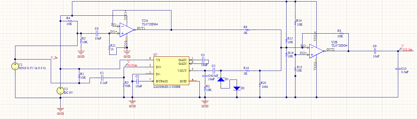
<p>After I had decided on the path I wanted to take, I booted up Altium Designer and began playing 
around with the simulation tools. I combined aspects from LTspice and my microelectronic circuit
lab to design both the soft and hard clipping aspects of the circuit, as well as impedance matching
the input and fuzz signal to allow for blending the two together.</p>

<figure>
  <img src="/assets/img/Pedal_Writeup_Images/Simulation.png" alt="Fuzz Circuit, Designed in Altium" />
  <figcaption>Fuzz Circuit Simulation in Altium Designer - Lucas Bucht 2026</figcaption>
</figure>

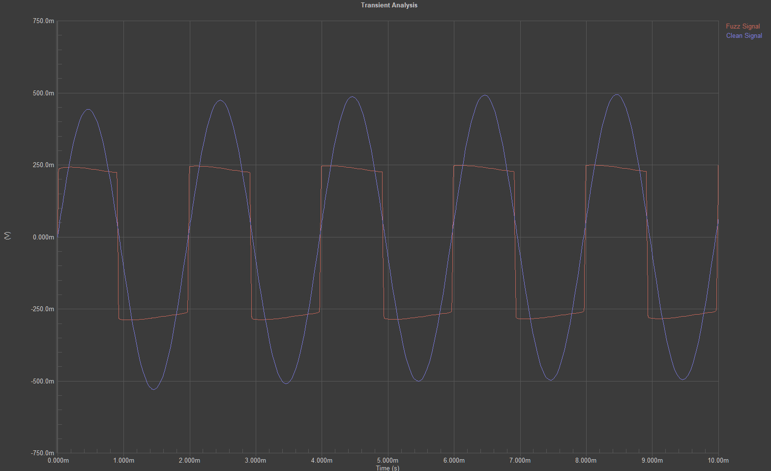
<p>Testing the completed circuit in Altium, I had come up with a circuit design that checked all the boxes: high 
dynamics with a smooth bottom, blend capabilities, and a sweet fuzz tone that cuts through the 
mix. To ensure the pedal would work when I assembled it, I simulated different frequencies to 
understand how the signal would react to the highs of a guitar and the lows of a bass. Across those 
instruments’ frequencies, from around 40Hz to 4kHz, the results remained consistent: a symmetrical hard clip 
with soft-clipped edges.</p>

<figure>
  <img src="/assets/img/Pedal_Writeup_Images/Fuzz.png" alt="Simulation Results Showing Hard-Clipped Tops, Smoothed Soft-Clipped Edges, and Slight Compression, Overlaid on the Clean Tone" />
  <figcaption>Fuzz Test at 500Hz — Lucas Bucht 2026</figcaption>
</figure>

<p><br /></p>

<h3 id="physical-prototyping">Physical Prototyping</h3>
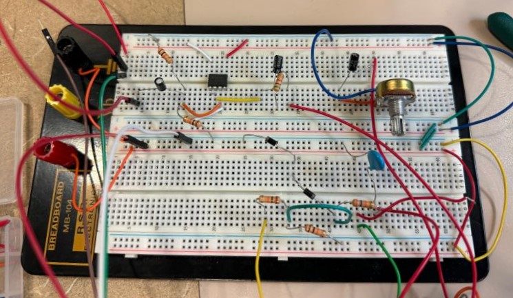
<p>Simulating the design that I wanted, I began to prototype with physical components. I had an 
oscilloscope hooked up to the output while adjusting resistor and capacitor values to cross-check 
the simulation results with reality. There were a couple of fixes I had to make, like adjusting the 
values of some of the resistors, but the first working prototype was solid. There was lots of noise 
due to the excessive jumper wires, but that was something I knew would fix itself on the pedal 
itself. I also only started with the tone knob, a potentiometer-controlled low-pass filter, to ensure 
the signal was passing through correctly.</p>

<figure>
  <img src="/assets/img/Pedal_Writeup_Images/Breadboard_Unfinished.jpg" alt="First working breadboard prototype — a lot of jumpers from things I tried and kept." />
  <figcaption>First Iterative Breadboard Prototype</figcaption>
</figure>

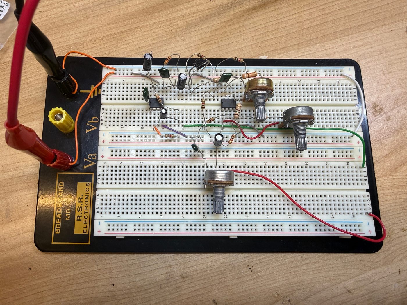
<p>Once I had confirmed the circuit working, I started adding more components like the <a href="https://www.ti.com/lit/ds/symlink/tl072.pdf">TL072 Dual Low-Noise, FET-Input Operational Amplifiers</a> 
and the additional potentiometers for volume and 
blending the clean and fuzzed signals together. It took a few more iterations of moving things 
around and swapping components to clean up the circuit in a way that minimized the need for 
jumper wires, but eventually I had reached a point on the breadboard where I couldn’t optimize the 
circuit any more.</p>

<figure>
  <img src="/assets/img/Pedal_Writeup_Images/Breadboard_Finished.jpg" alt="Finished working breadboard prototype — no more jumpers and cleaned up circuit paths." />
  <figcaption>Final Fuzz Circuit Prototype — Lucas Bucht 2026</figcaption>
</figure>

<p>Having the circuit built out on the breadboard allowed me to make changes to the circuit in real 
time and hear the differences. The next step was to take these changes and apply them on a 
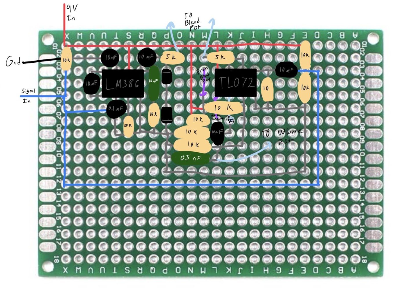
protoboard, the final step before full assembly. I spent hours drawing out multiple iterations of how 
I wanted to arrange the components on the protoboard, each one changing either the spacing, part 
orientation, or the wiring. Keeping things as concise as possible is tough when there are a lot of 
components and not a lot of room, but spending the time optimizing the protoboard saved me so 
much grief in the long run. Once I started soldering, I was too deep in the process to stop and take 
pictures, so this sketch is the layout I actually worked from.</p>

<figure>
  <img src="/assets/img/Pedal_Writeup_Images/Protoboard.jpg" alt="A drawing of where I put the parts on the protoboard." />
  <figcaption>Fuzz Pedal Schematic Planned Out on Protoboard</figcaption>
</figure>

<p><br /></p>

<h3 id="assembly">Assembly</h3>
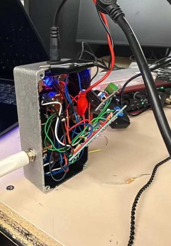
<p>The assembly process was not pretty, but determination to complete this two-year-long project 
helped me persevere. Soldering the components onto the protoboard wasn’t too much of a hassle, 
but getting everything to fit in the pedal housing was a different story. To make it easier on myself, I 
left a lot of the wires longer than necessary so that I could solder things to the board while they 
were already in the enclosure. This actually ended up making it harder since I had to work around 
the wires. After a couple frustrating days of trying and failing to get things to fit, I shortened the 
wires and managed to fit everything inside the case, albeit not very efficiently. Making sure the 
pedal worked, I incrementally shortened the wires to the potentiometers and verified each iteration. 
Eventually I got to a place where I was happy and had no concerns about the pedal.</p>

<figure>
  <img src="/assets/img/Pedal_Writeup_Images/Messy_Pedal.jpg" alt="A picture of the rear of the pedal enclosure with loose wires hanging out." />
  <figcaption>The Mess of Wires that Plagued My Pedal</figcaption>
</figure>

<p><br /></p>

<h3 id="final-thoughts">Final Thoughts</h3>
<p>I never thought in a million years that I would be able to say that I built my own guitar pedal. It was 
always just a fantasy that I’d get around to eventually or a dream just out of reach. In my mind, this 
project culminates everything I’m working towards in my degree. When I started out as a freshman 
at Pitt, I had no idea what I wanted to do or if I even wanted to be an electrical engineer at all. This 
project showed me what it means to be an engineer: weeks of struggle and late nights of 
confusion, but also learning new things and stepping out of my comfort zone. By pushing myself to 
my limits, I experienced so much growth in this field and gained so much confidence in myself and 
what I can do. My advice for anyone interested in trying something like this: <em>take the first step</em>. You 
may not get it right on the first try (or the second or third), but what matters is learning from that 
experience. There is so much knowledge to be gained from new experiences, all you have to do is 
start.</p>

<figure>
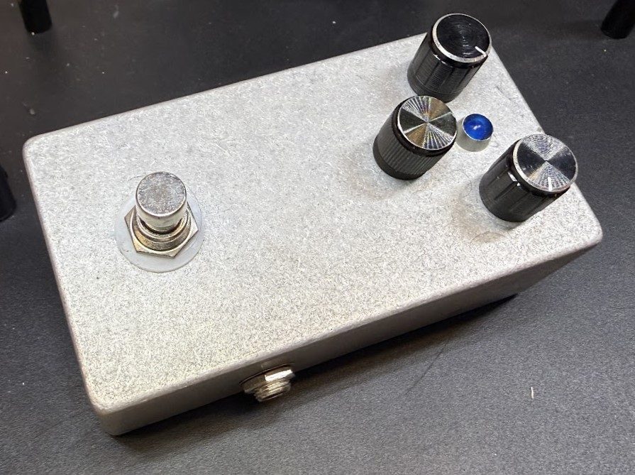
  <img src="/assets/img/Pedal_Writeup_Images/Clean_Pedal.JPG" alt="Finished fuzz pedal in the enclosure and looking good." />
  <figcaption>The Finished Pedal</figcaption>
</figure>

<!--
<figure>
    <audio controls>
        <source src="/assets/audio/fuzz-guitar.mp3" type="audio/mpeg">
    </audio>
    <figcaption>Fuzz Pedal Demo — Guitar</figcaption>
</figure>

<figure>
    <audio controls>
        <source src="/assets/audio/fuzz-bass.mp3" type="audio/mpeg">
    </audio>
    <figcaption>Fuzz Pedal Demo — Bass</figcaption>
</figure>
-->]]></content><author><name>Lucas Bucht</name><email>buchtlu@gmail.com</email></author><summary type="html"><![CDATA[]]></summary></entry><entry><title type="html">How I Made: Sump One-Way Valve</title><link href="https://lucasbucht.github.io/blog/2026/05/30/sump-pump/" rel="alternate" type="text/html" title="How I Made: Sump One-Way Valve" /><published>2026-05-30T00:00:00+00:00</published><updated>2026-05-30T00:00:00+00:00</updated><id>https://lucasbucht.github.io/blog/2026/05/30/sump-pump</id><content type="html" xml:base="https://lucasbucht.github.io/blog/2026/05/30/sump-pump/"><![CDATA[<hr />

<h3 id="backstory">Backstory</h3>
<p>Before the deck on our house was constructed, the sump pump exit pipe sat right next to the foundation of our house, an obvious problem that didn’t really have a clear solution. Since the pipe exit wasn’t already underground, the easiest answer was to extend the pipe once the deck was built so the water would disperse further from the house and keep our foundation dry. That longer pipe, however, led to a different problem: <em>animals</em>. Small critters like mice, voles, and lizards seemed to enjoy climbing into this pipe and getting stuck, which caused the pipes to back up and risk damaging the sump system entirely. This led to my dad putting a mesh screen on the front of the pipe. While it kept things out of the pipes, it also kept things in, namely grass. After mowing the lawn, any grass that got into the drain of our basement stairs would go straight through the sump and out the exit pipe. Having the mesh there meant that every time it rained, we would have to take off the mesh and clean it out so that the water didn’t back up in the pipe, the exact same problem we were trying to solve with the mesh in the first place.</p>

<p><br /></p>

<h3 id="initial-brainstorming---autodesk-fusion-360">Initial Brainstorming - Autodesk Fusion 360</h3>
<h4 id="iteration-1">Iteration 1</h4>
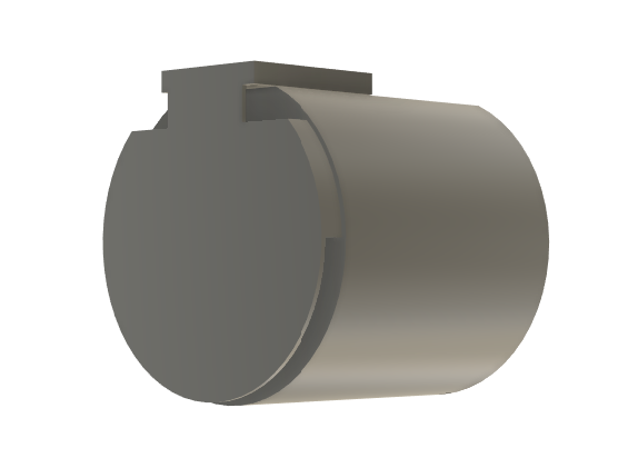
<p>This problem had two important parts: water and grass can go out easily while keeping the valve normally closed to the outside. While it seemed like an easy problem to solve, I had to design something that was easily 3D-printable, could withstand the elements, and could handle the immense pressure of the water being shot out of the sump. My initial thought process was to use a rigid flap that sat close to the pipe exit and could bend up and out of the way by the pressure of the water. I started with a tight-fitting base around the end of the PVC pipe and then worked on a flap that would fit over the hole while still allowing water to force it open.</p>

<figure>
  <img src="/assets/img/Sump_Writeup_Images/InitialDesign1.png" alt="First Design, created in Fusion 360" />
  <figcaption>Initial Design for a Rigid-Flapped Pipe Cover (2024)</figcaption>
</figure>

<p>While very easy to print, this initial design had a major design flaw I should’ve seen coming: water can get between the flap and the base, creating a vacuum seal and causing water to sit behind the flap instead of draining. This, again, caused the same exact backup that we were trying to avoid with the new pipe cover, so back to the drawing board.</p>

<h4 id="iteration-2">Iteration 2</h4>
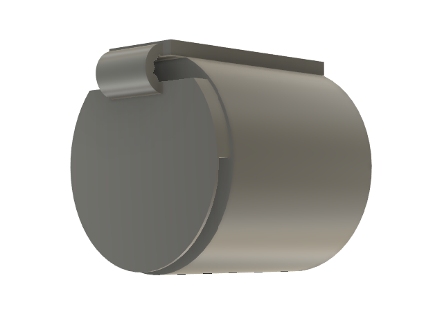
<p>The second time around, I thought I’d repeat the same idea but design the flap in a way that it can’t create a seal. I added small notches to the top of the flap that would keep it separated no matter how much water got between the two. I also changed how thick the flap was, increasing its flexibility at the cost of some durability.</p>

<figure>
  <img src="/assets/img/Sump_Writeup_Images/InitialDesign2.png" alt="Second Design, created in Fusion 360" />
  <figcaption>Second Design for a Rigid-Flapped Pipe Cover (2024)</figcaption>
</figure>

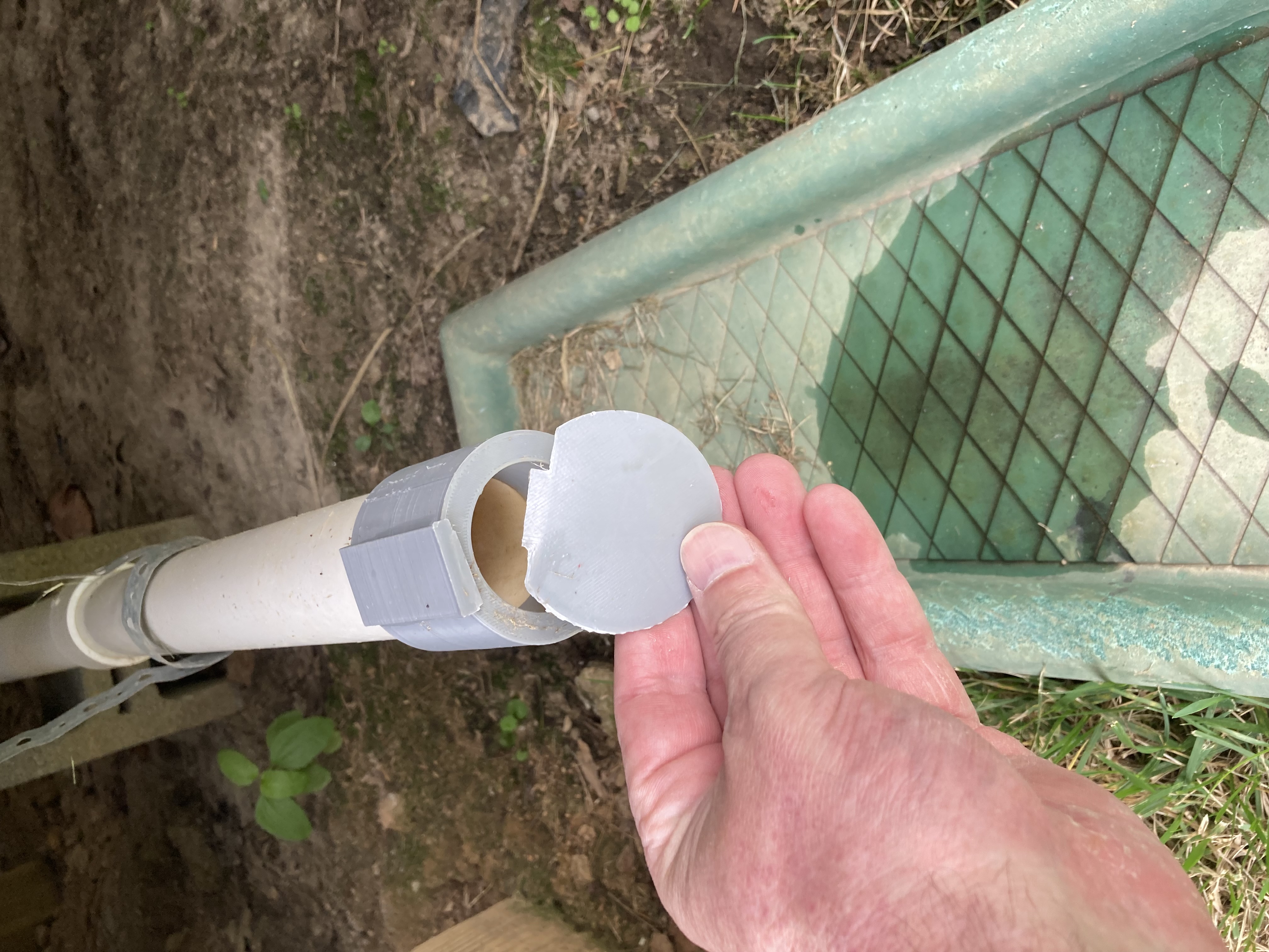
<p>This second design had a lot of potential, but as we’ll see, it did not satisfy all the requirements I had set for the project. To its credit, this second iteration was super easy to print and could be swapped onto the base of the original, keeping the total new print time at under an hour. The biggest issue this one had was withstanding the elements. I assumed that since the first one had withstood the elements, this one would be able to as well, but I was sadly mistaken. Since the flap actually moved this time and wasn’t stuck to the base, the heat and cold eventually took its toll and snapped the flap at the stress concentration point, right where the flap thins out. Obviously I should’ve seen it coming, but I was still disappointed when I was told that the cover had failed.</p>

<figure>
  <img src="/assets/img/Sump_Writeup_Images/CriticalFailure1.jpeg" alt="Second Design (Critically Failed)" />
  <figcaption>Bending Failure of the Second Design</figcaption>
</figure>

<h4 id="iteration-3">Iteration 3</h4>
<p>After taking a look at why iteration 2 failed, I decided to try and rework how the base and flap connected to each other. I started by changing the filament from PLA to PETG, a less flexible but more stable material, in hopes that it would solve some of my weather-related failure issues. I then changed the shape from a flat rectangle connection joint to a circular joint and added some relief cutouts to give the material added flexibility. The hope was that using a circular joint would allow the flap to bend upward somewhat while the water was pushing out on it, then snap back when the water stopped. This method also allowed for a lot more pressure to be applied on the flap since the area of connectivity changed from a thin rectangle above the flap to a thick circle in front of the flap. This changes the type of stress needed to push the cover to failure from bending to shear. With the original 2 designs, since the flap was printed as one flat plane, the failure point was caused by a perpendicular force (water) pushing on it until it split. With design 3, I changed the topology of the flap from the whole thing being a single plane to adding extra support in a third dimension. This meant that the perpendicular force no longer posed a threat to the connection, rendering this the most successful of the 3 so far, checking 2 of the three boxes.</p>

<figure>
  <img src="/assets/img/Sump_Writeup_Images/InitialDesign3.png" alt="Third Design, created in Fusion 360" />
  <figcaption>Third Design for a Rigid-Flapped Pipe Cover (2024)</figcaption>
</figure>

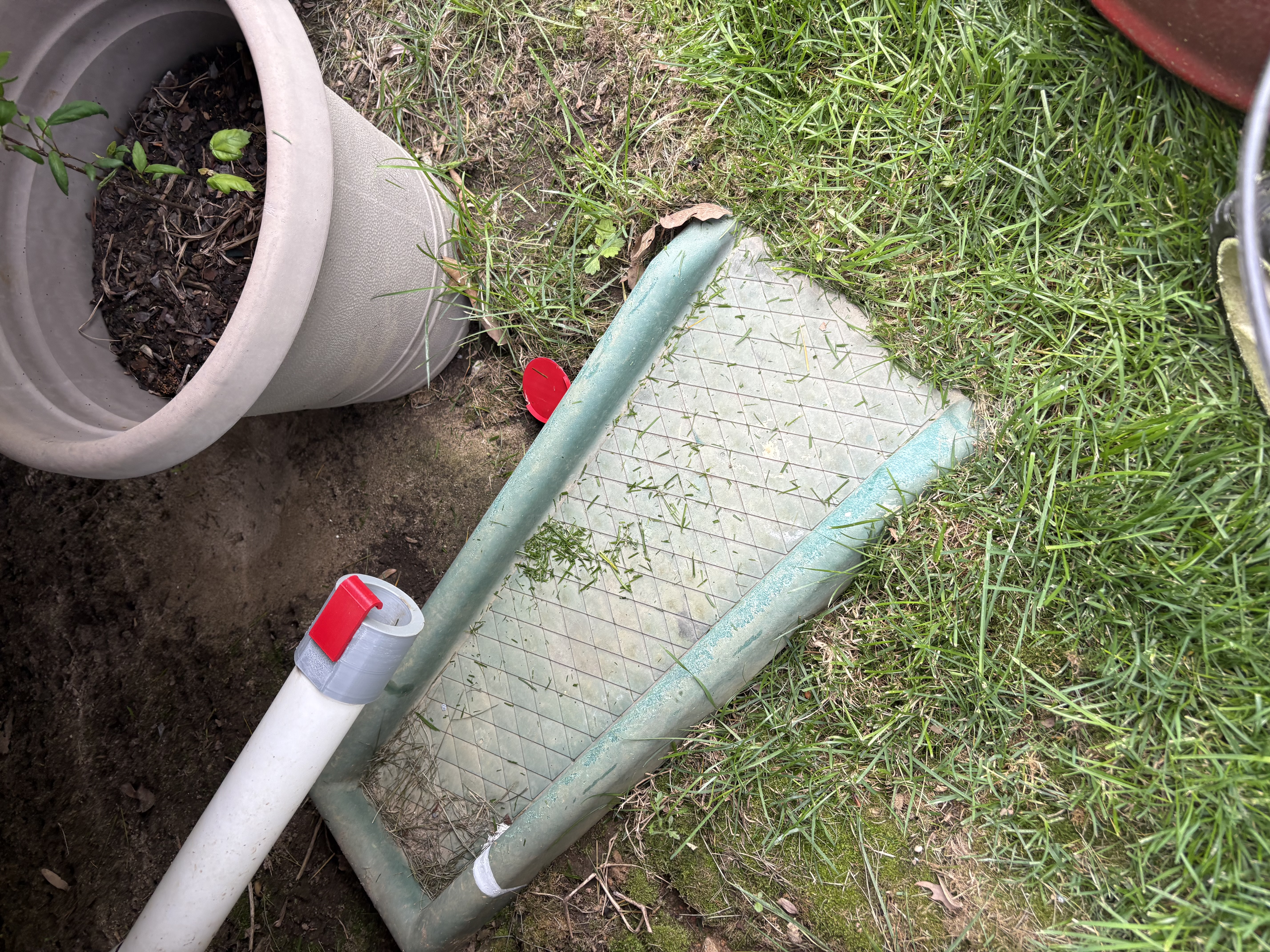
<p>Unfortunately for me, not all 3 boxes were checked. While it was much stronger against the water and was still fairly easy to print, this design also did not hold up against the outdoors, but it lasted significantly longer than my other two iterations. After holding up for roughly 8 months, the changing temperature and constant sun exposure caused a few of the layers to expand and contract, leading to layer adhesion weakening. This weakened layer adhesion, along with the weather, caused the cover assembly to fail. This proved that I needed to change my design since the rigid design obviously wasn’t working.</p>

<figure>
  <img src="/assets/img/Sump_Writeup_Images/CriticalFailure2.jpeg" alt="Third Design (Critically Failed)" />
  <figcaption>Shear Failure of the Third Design</figcaption>
</figure>

<h4 id="iteration-4---success">Iteration 4 - Success</h4>
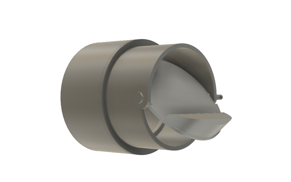
<p>After over a year of trial and error, I finally decided to change my approach from a rigid, flap-oriented sump pump exit cover to a dynamic cover. I did some research and found a couple one-way valves designed to keep smells out of showers by having a counterweight keep the valve closed until water pushes it open. I really liked this design because it was exactly what I wanted, just in a different orientation. Since the shower valve is designed for a vertical pipe, I had to modify the design to work in a horizontal manner. This was surprisingly difficult, since the counterweight didn’t function correctly when used horizontally, and changing the counterweight made the print a lot more complex. The next month or so was spent designing, optimizing, and testing this single iteration, eventually leading to something that actually worked: a sump pump exit pipe cover that stayed closed when water wasn’t coming out of it.</p>

<figure>
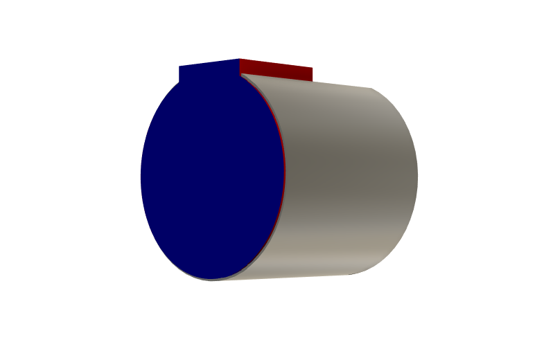
  <img src="/assets/img/Sump_Writeup_Images/InitialDesign4.png" alt="Fourth and Final Design, created in Fusion 360" />
  <figcaption>Final Design for a Dynamic-Flapped Pipe Cover (2025)</figcaption>
</figure>

<p>Succeeding here showed that the ideas I had were important to the final design, even if the final design required throwing out everything I’d been trying. By testing and figuring out what didn’t work, I was able to get an idea of how to move forward in a productive way. The most defining part of the experience was designing something that I think is great, waiting a few months, and then it critically failing and causing me to start over. I would’ve much preferred to have my designs fail in a day, a week, or even a month, but most of the failures didn’t show up until months later, after I’d already celebrated my wins and felt accomplished. This mimics real industry experience because it’s common to have a product that is researched and works well in the short term, but then is later found to have some critical fault. The most important takeaway is that just because a design keeps failing doesn’t mean it’s a bad design. Every failure is data leading you towards success, even if it feels like a setback.</p>

<h3 id="video-of-pipe-cover-in-action">Video of Pipe Cover in Action</h3>

<figure>
  <video controls="" width="100%">
    <source src="/assets/video/CoverInAction.mp4" type="video/mp4" />
  </video>
  <figcaption>Valve opening under flow, closing once water stops.</figcaption>
</figure>]]></content><author><name>Lucas Bucht</name><email>buchtlu@gmail.com</email></author><summary type="html"><![CDATA[]]></summary></entry></feed>