How I Made: Sump One-Way Valve
Backstory
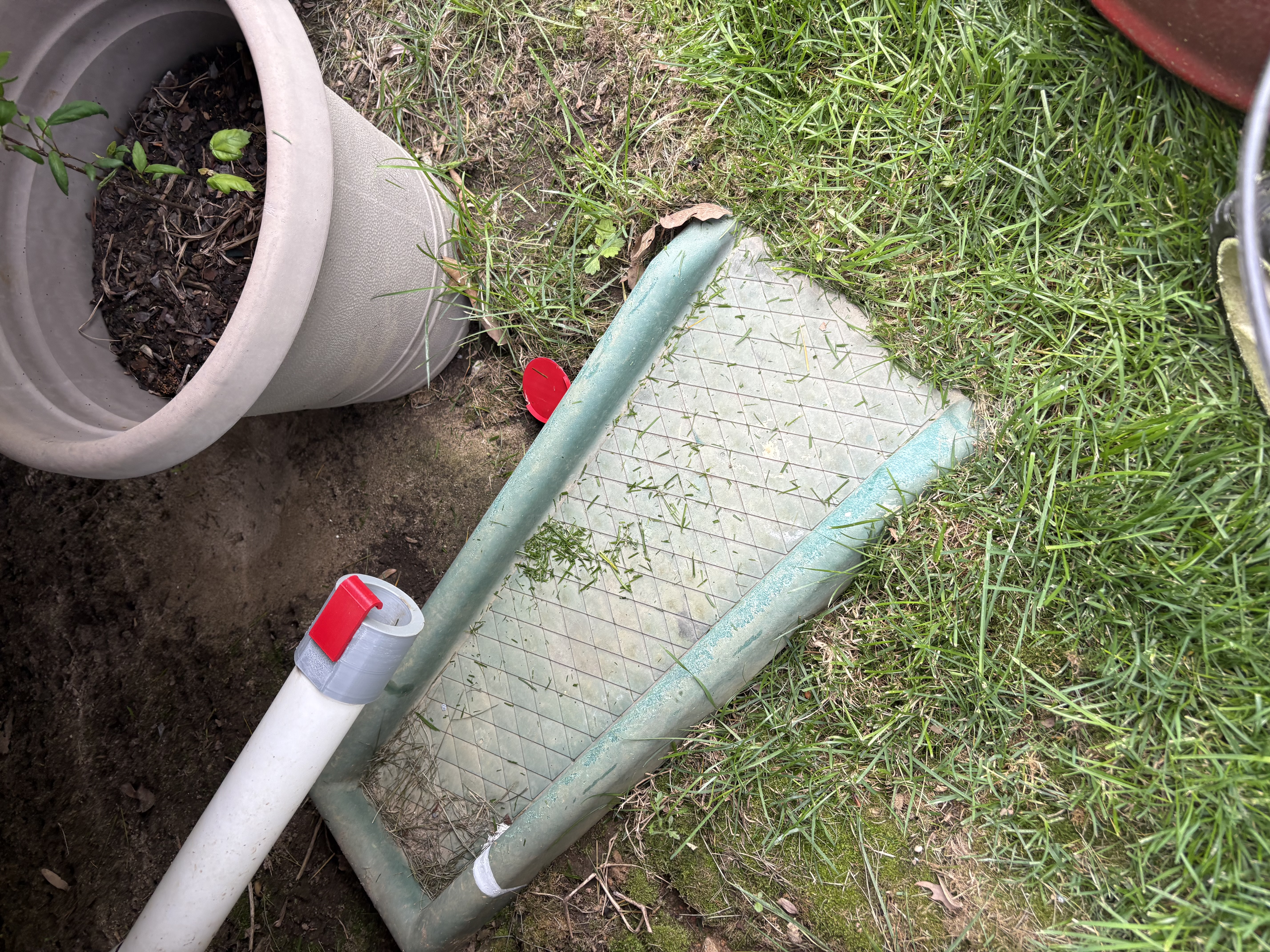
Before the deck on our house was constructed, the sump pump exit pipe sat right next to the foundation of our house, an obvious problem that didn’t really have a clear solution. Since the pipe exit wasn’t already underground, the easiest answer was to extend the pipe once the deck was built so the water would disperse further from the house and keep our foundation dry. That longer pipe, however, led to a different problem: animals. Small critters like mice, voles, and lizards seemed to enjoy climbing into this pipe and getting stuck, which caused the pipes to back up and risk damaging the sump system entirely. This led to my dad putting a mesh screen on the front of the pipe. While it kept things out of the pipes, it also kept things in, namely grass. After mowing the lawn, any grass that got into the drain of our basement stairs would go straight through the sump and out the exit pipe. Having the mesh there meant that every time it rained, we would have to take off the mesh and clean it out so that the water didn’t back up in the pipe, the exact same problem we were trying to solve with the mesh in the first place.
Initial Brainstorming - Autodesk Fusion 360
Iteration 1
This problem had two important parts: water and grass can go out easily while keeping the valve normally closed to the outside. While it seemed like an easy problem to solve, I had to design something that was easily 3D-printable, could withstand the elements, and could handle the immense pressure of the water being shot out of the sump. My initial thought process was to use a rigid flap that sat close to the pipe exit and could bend up and out of the way by the pressure of the water. I started with a tight-fitting base around the end of the PVC pipe and then worked on a flap that would fit over the hole while still allowing water to force it open.
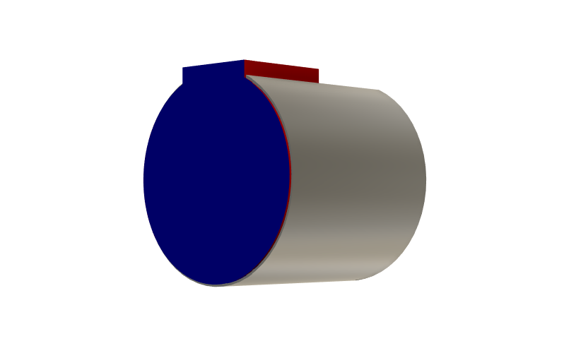
While very easy to print, this initial design had a major design flaw I should’ve seen coming: water can get between the flap and the base, creating a vacuum seal and causing water to sit behind the flap instead of draining. This, again, caused the same exact backup that we were trying to avoid with the new pipe cover, so back to the drawing board.
Iteration 2
The second time around, I thought I’d repeat the same idea but design the flap in a way that it can’t create a seal. I added small notches to the top of the flap that would keep it separated no matter how much water got between the two. I also changed how thick the flap was, increasing its flexibility at the cost of some durability.
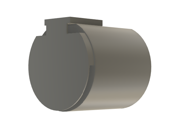
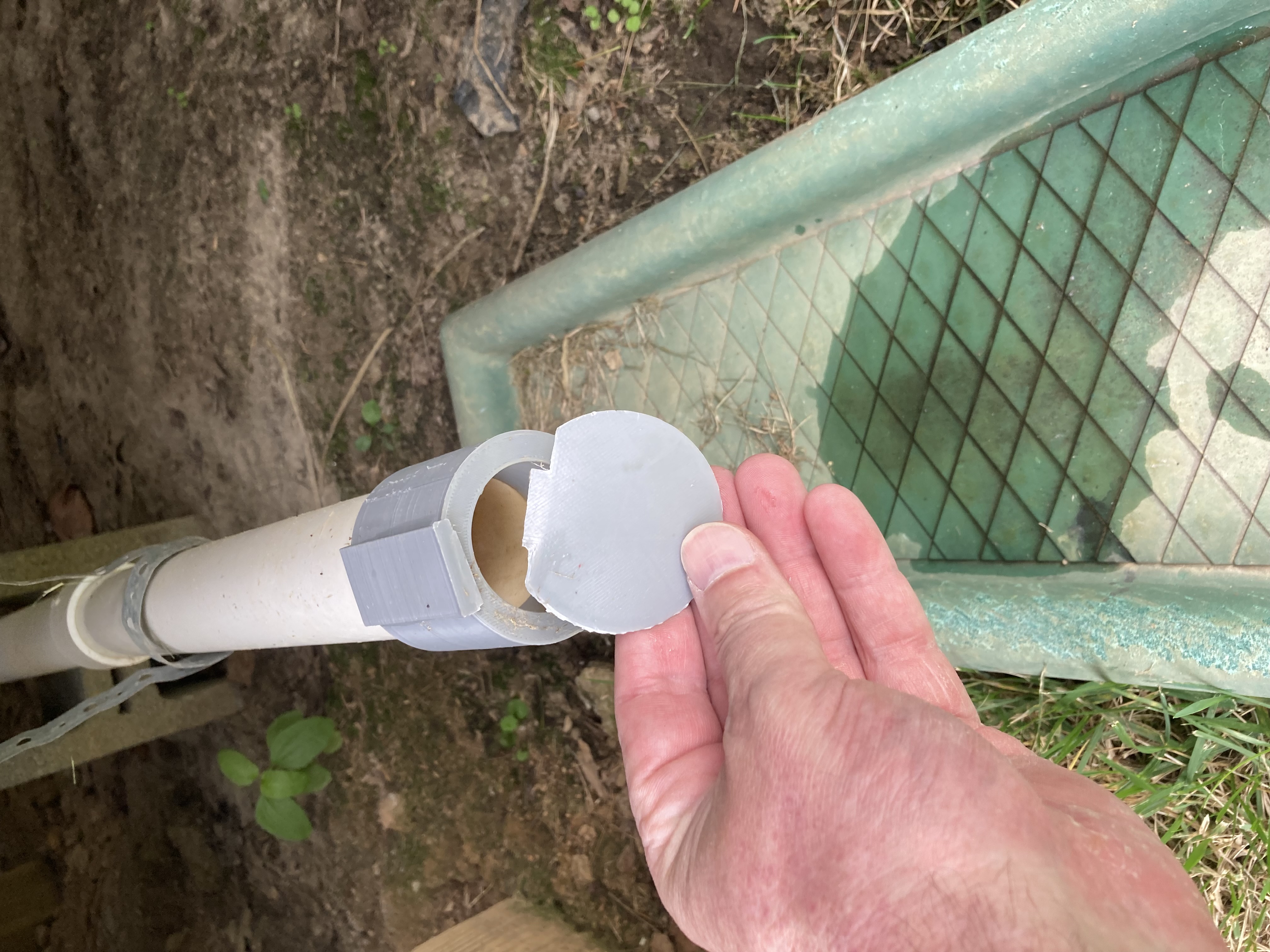
This second design had a lot of potential, but as we’ll see, it did not satisfy all the requirements I had set for the project. To its credit, this second iteration was super easy to print and could be swapped onto the base of the original, keeping the total new print time at under an hour. The biggest issue this one had was withstanding the elements. I assumed that since the first one had withstood the elements, this one would be able to as well, but I was sadly mistaken. Since the flap actually moved this time and wasn’t stuck to the base, the heat and cold eventually took its toll and snapped the flap at the stress concentration point, right where the flap thins out. Obviously I should’ve seen it coming, but I was still disappointed when I was told that the cover had failed.
Iteration 3
After taking a look at why iteration 2 failed, I decided to try and rework how the base and flap connected to each other. I started by changing the filament from PLA to PETG, a less flexible but more stable material, in hopes that it would solve some of my weather-related failure issues. I then changed the shape from a flat rectangle connection joint to a circular joint and added some relief cutouts to give the material added flexibility. The hope was that using a circular joint would allow the flap to bend upward somewhat while the water was pushing out on it, then snap back when the water stopped. This method also allowed for a lot more pressure to be applied on the flap since the area of connectivity changed from a thin rectangle above the flap to a thick circle in front of the flap. This changes the type of stress needed to push the cover to failure from bending to shear. With the original 2 designs, since the flap was printed as one flat plane, the failure point was caused by a perpendicular force (water) pushing on it until it split. With design 3, I changed the topology of the flap from the whole thing being a single plane to adding extra support in a third dimension. This meant that the perpendicular force no longer posed a threat to the connection, rendering this the most successful of the 3 so far, checking 2 of the three boxes.
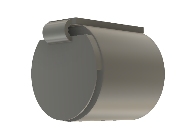
Unfortunately for me, not all 3 boxes were checked. While it was much stronger against the water and was still fairly easy to print, this design also did not hold up against the outdoors, but it lasted significantly longer than my other two iterations. After holding up for roughly 8 months, the changing temperature and constant sun exposure caused a few of the layers to expand and contract, leading to layer adhesion weakening. This weakened layer adhesion, along with the weather, caused the cover assembly to fail. This proved that I needed to change my design since the rigid design obviously wasn’t working.
Iteration 4 - Success
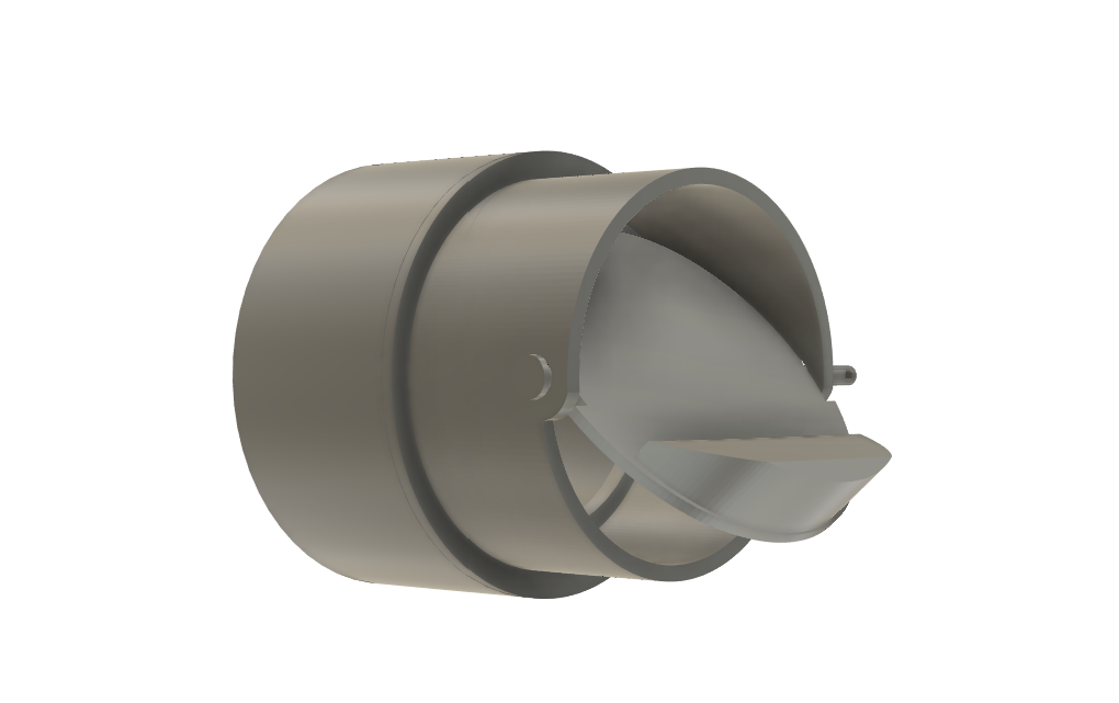
After over a year of trial and error, I finally decided to change my approach from a rigid, flap-oriented sump pump exit cover to a dynamic cover. I did some research and found a couple one-way valves designed to keep smells out of showers by having a counterweight keep the valve closed until water pushes it open. I really liked this design because it was exactly what I wanted, just in a different orientation. Since the shower valve is designed for a vertical pipe, I had to modify the design to work in a horizontal manner. This was surprisingly difficult, since the counterweight didn’t function correctly when used horizontally, and changing the counterweight made the print a lot more complex. The next month or so was spent designing, optimizing, and testing this single iteration, eventually leading to something that actually worked: a sump pump exit pipe cover that stayed closed when water wasn’t coming out of it.
Succeeding here showed that the ideas I had were important to the final design, even if the final design required throwing out everything I’d been trying. By testing and figuring out what didn’t work, I was able to get an idea of how to move forward in a productive way. The most defining part of the experience was designing something that I think is great, waiting a few months, and then it critically failing and causing me to start over. I would’ve much preferred to have my designs fail in a day, a week, or even a month, but most of the failures didn’t show up until months later, after I’d already celebrated my wins and felt accomplished. This mimics real industry experience because it’s common to have a product that is researched and works well in the short term, but then is later found to have some critical fault. The most important takeaway is that just because a design keeps failing doesn’t mean it’s a bad design. Every failure is data leading you towards success, even if it feels like a setback.