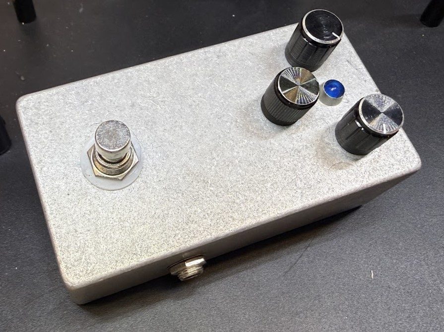
How I Made: Guitar Fuzz Pedal
Backstory
I started playing guitar 3 years ago, and one of the things that fascinated me the most when I started was testing out different pedals. I was blown away by the different sounds you could achieve using discrete components and an analog signal. My first impression of a guitar pedal was a basic volume/wah pedal, an extremely simple circuit and common pedal that you find on most pedalboards. After experimenting with the vol/wah pedal, I started collecting pedals and assembling my own pedalboard. Over the next year or so, I collected used pedals and assembled a board that allowed me to achieve almost every sound I desired, except for one: Fuzz.
Initial Brainstorming
One of the sounds I wanted out of my pedal was the smooth and thick fuzz sound of a Big Muff, while keeping a lot of the articulation like a Fuzz Face. While researching, I decided to try and mimic the Big Muff Op-Amp sound since it had the body and resonance I wanted. While researching, I found many op-amps that had the desired signal response, but I landed on the LM386 Low Voltage Audio Power Amplifier. While many IC chips had similar signal response, the LM386 had 2 key features that set it apart from other op-amps: adjustable gain and self-centering output. Placing different capacitors between pins 1 and 8, the gain can be pushed from 20× to 200×, achieving the hard-clipping sound of an aggressive fuzz pedal. This signal response works well with the self-centering input since adding two clipping diodes to the output created a very smooth, symmetrical, soft clip that keeps the dynamics while toning down the harshness.
Altium Simulation
After I had decided on the path I wanted to take, I booted up Altium Designer and began playing around with the simulation tools. I combined aspects from LTspice and my microelectronic circuit lab to design both the soft and hard clipping aspects of the circuit, as well as impedance matching the input and fuzz signal to allow for blending the two together.
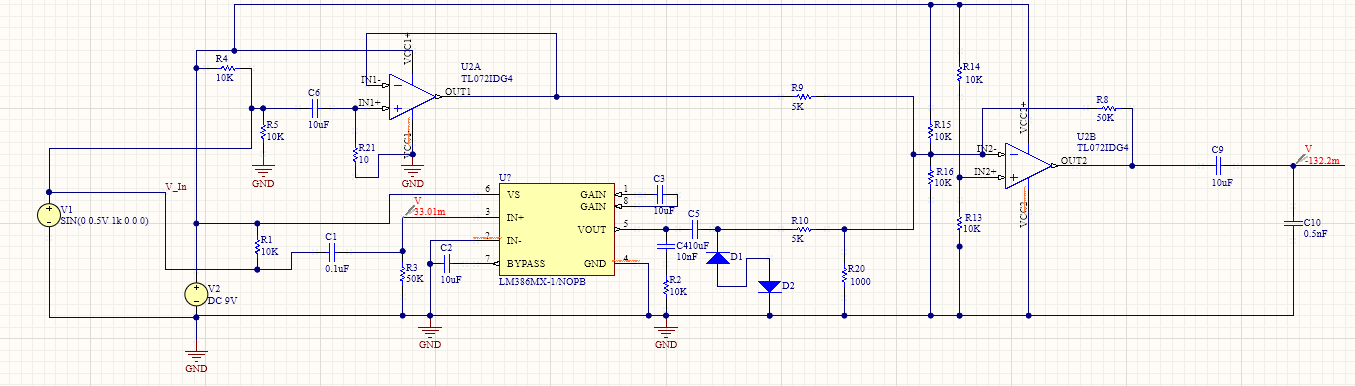
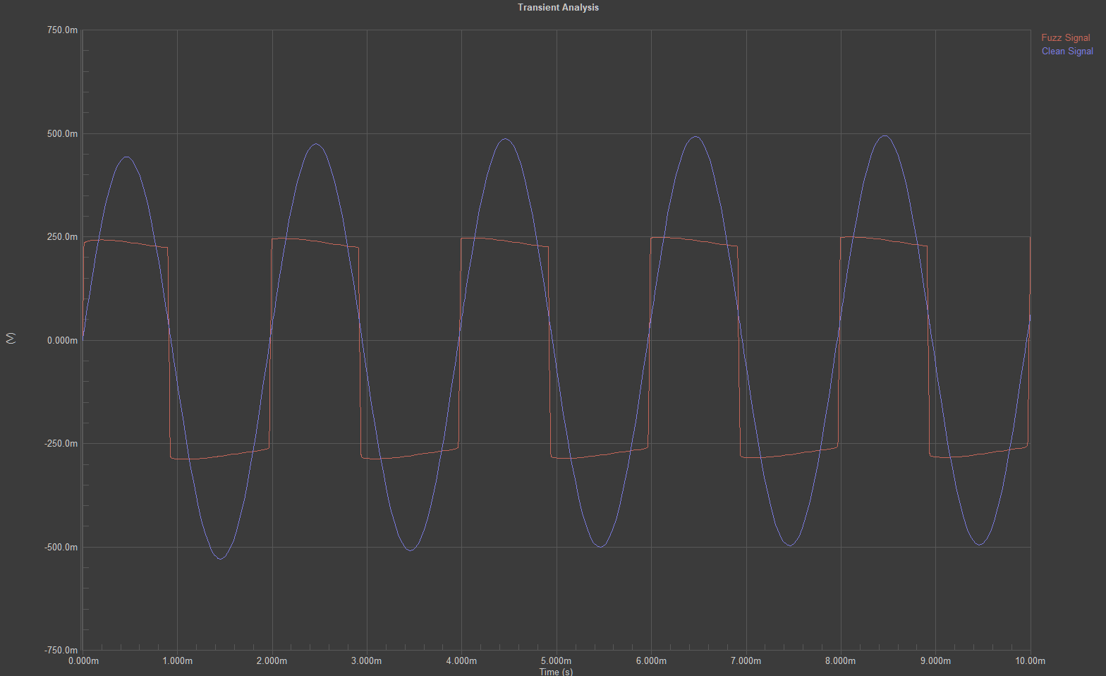
Testing the completed circuit in Altium, I had come up with a circuit design that checked all the boxes: high dynamics with a smooth bottom, blend capabilities, and a sweet fuzz tone that cuts through the mix. To ensure the pedal would work when I assembled it, I simulated different frequencies to understand how the signal would react to the highs of a guitar and the lows of a bass. Across those instruments’ frequencies, from around 40Hz to 4kHz, the results remained consistent: a symmetrical hard clip with soft-clipped edges.
Physical Prototyping
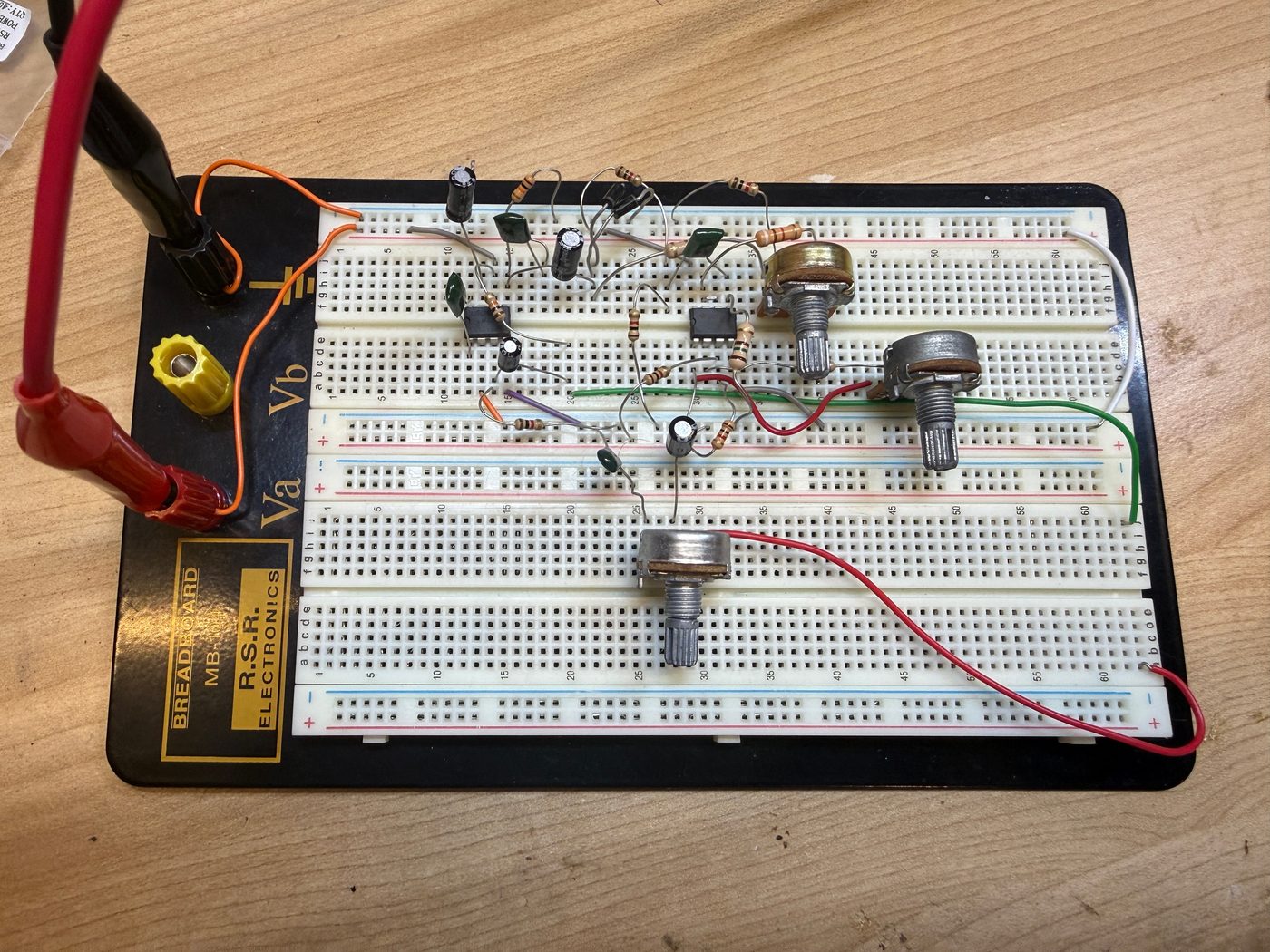
Simulating the design that I wanted, I began to prototype with physical components. I had an oscilloscope hooked up to the output while adjusting resistor and capacitor values to cross-check the simulation results with reality. There were a couple of fixes I had to make, like adjusting the values of some of the resistors, but the first working prototype was solid. There was lots of noise due to the excessive jumper wires, but that was something I knew would fix itself on the pedal itself. I also only started with the tone knob, a potentiometer-controlled low-pass filter, to ensure the signal was passing through correctly.
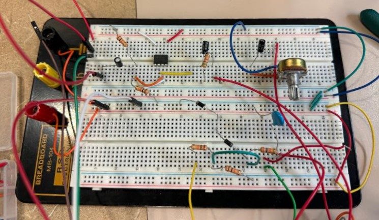
Once I had confirmed the circuit working, I started adding more components like the TL072 Dual Low-Noise, FET-Input Operational Amplifiers and the additional potentiometers for volume and blending the clean and fuzzed signals together. It took a few more iterations of moving things around and swapping components to clean up the circuit in a way that minimized the need for jumper wires, but eventually I had reached a point on the breadboard where I couldn’t optimize the circuit any more.
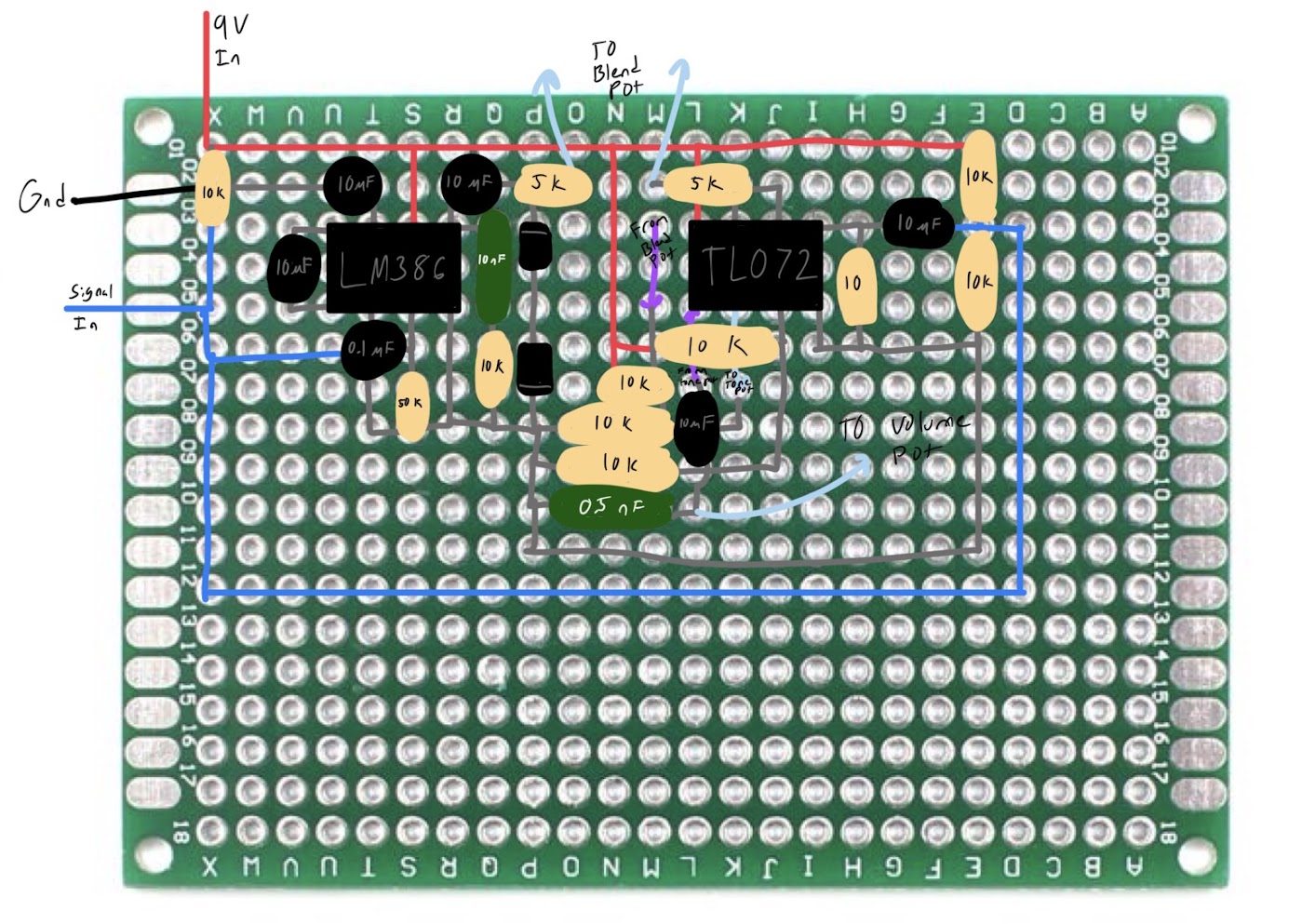
Having the circuit built out on the breadboard allowed me to make changes to the circuit in real time and hear the differences. The next step was to take these changes and apply them on a protoboard, the final step before full assembly. I spent hours drawing out multiple iterations of how I wanted to arrange the components on the protoboard, each one changing either the spacing, part orientation, or the wiring. Keeping things as concise as possible is tough when there are a lot of components and not a lot of room, but spending the time optimizing the protoboard saved me so much grief in the long run. Once I started soldering, I was too deep in the process to stop and take pictures, so this sketch is the layout I actually worked from.
Assembly
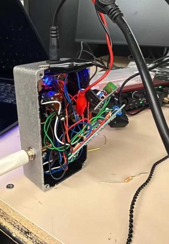
The assembly process was not pretty, but determination to complete this two-year-long project helped me persevere. Soldering the components onto the protoboard wasn’t too much of a hassle, but getting everything to fit in the pedal housing was a different story. To make it easier on myself, I left a lot of the wires longer than necessary so that I could solder things to the board while they were already in the enclosure. This actually ended up making it harder since I had to work around the wires. After a couple frustrating days of trying and failing to get things to fit, I shortened the wires and managed to fit everything inside the case, albeit not very efficiently. Making sure the pedal worked, I incrementally shortened the wires to the potentiometers and verified each iteration. Eventually I got to a place where I was happy and had no concerns about the pedal.
Final Thoughts
I never thought in a million years that I would be able to say that I built my own guitar pedal. It was always just a fantasy that I’d get around to eventually or a dream just out of reach. In my mind, this project culminates everything I’m working towards in my degree. When I started out as a freshman at Pitt, I had no idea what I wanted to do or if I even wanted to be an electrical engineer at all. This project showed me what it means to be an engineer: weeks of struggle and late nights of confusion, but also learning new things and stepping out of my comfort zone. By pushing myself to my limits, I experienced so much growth in this field and gained so much confidence in myself and what I can do. My advice for anyone interested in trying something like this: take the first step. You may not get it right on the first try (or the second or third), but what matters is learning from that experience. There is so much knowledge to be gained from new experiences, all you have to do is start.